Over the last couple of months (pretty much ever since I packed up my workshop back home really) I’ve been thinking about a prototyping machine. Just something small. Basically a 3D printer, router, engraver, laser engraver, pick and place, general purpose combination CNC…thing. Not all of these things at once obviously. But what it could eventually become.
But above that I think it will be a pretty good project for me while I’m traveling. It involves a lot of research, planning, design and testing, both mechanical and electrically. So it will keep me busy for a while in a variety of areas, won’t have any large or expensive parts till its quite far through when I have committed to making it (and should only need to buy parts once if its well planned out 😛 ). But after all the planning, research, design and making it, it should be an easily transportable tool for me to use in lieu of having an actual workshop. Well that’s the idea at this stage anyway.
What are the must haves / restrictions / requirements / scope:
- Cheap. Ideally less than $500 NZD parts cost (excluding research parts). But this could be extended depending on my circumstances at the time.
- Lightweight. Less than 8kg would be good.
- Compact. To collapse or fold-up (for example), to fit in a normal suitcase with other stuff
- Accurate. Ideally <+-0.1mm X, Y positioning and <+-0.05mm Z positioning.
- Have ability to interchange heads for multiple uses.
- As rigid as possible. An arm design is never going to be very rigid, so some flex is expected.
- Have a working area of at least 150x150x50mm : X Y Z (about the size of a standard piece of bare PCB).
- Have a stand alone controller. No computer necessary to continue operation after programming i.e run off an SD card.
Secondary goals, I don’t need these but they would be cool to try and have:
- Use DIY brushless servo motors. Because I hate the sound of stepper motors and I want to learn more about brushless motors.
- Use 32bit ARM or similar based MCU on the main controller. I want to learn to program new devices.
- Look interesting, clean and professional. Well as professional and clean as I can anyway.
- Have as little wiring as possible. Daisy chained communication and power lines for example.
So now all of the boring goals are out of the way, what am I thinking it will look like? Any ideas on the design? Parts?
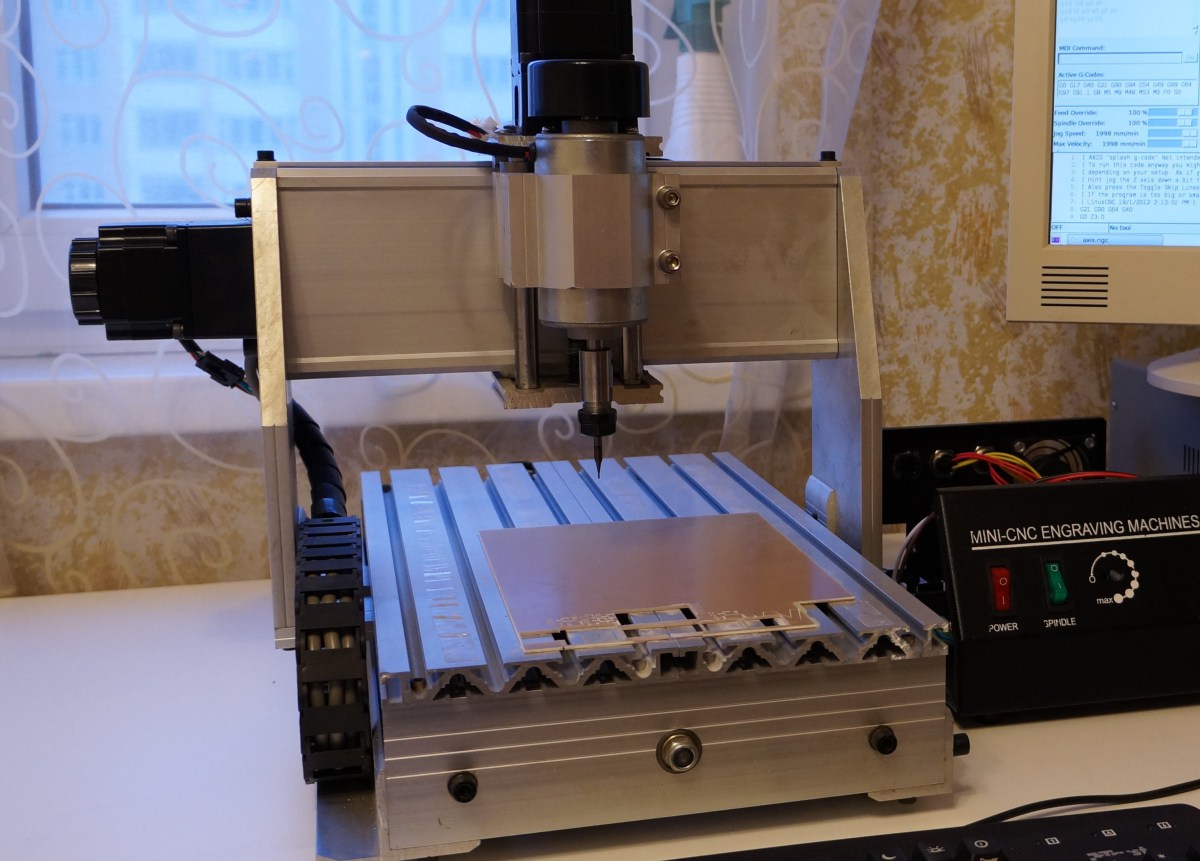
Hahaha yea actually. Recently did a bus tour around mainland Europe so I had lots of down time on long journeys to think/ draw it out. After a bit of research currently I’m inclining towards a planer arm type CNC. Something like this, but my design:
(I would actually go for this but it isn’t in production yet and I don’t really like spending a lot of money on things when I’ll be missing out on learning. Within reason of course.)

http://www.fluxintegration.com/pages/flx-arm
Now that I had an idea of how the thing will be moving, I started thinking about the how, did some concept drawing and tightened down some of the technical details. For example:
- On axis magnetic, rotary position sensors / encoders. From what I’ve found so far they are the most accurate and easiest to use for the price.
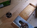
- Laser / Water Jet cut Arm plates. Allows me to custom design the arms without expensive post machining (I’ll do the simple stuff like countersinking etc) and not that expensive either.
- Off the shelf, Needle Roller thrust bearings and Ball bearings. Without precision machining in the arm joints I’m a bit limited for choice :S
- A cylindrical type clamp in the B axis arm for the interchangeable heads. Just the easiest for the arm and the heads.
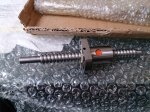
- Ball screw for the Z Axis (up and down). Simple and precise.
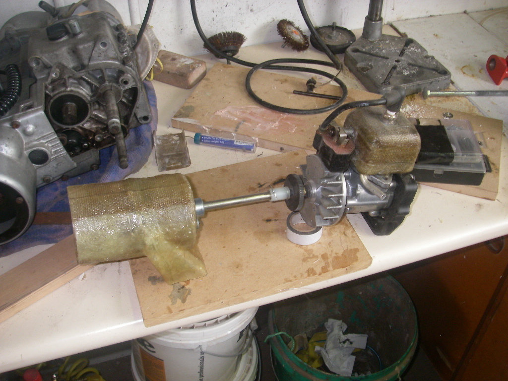
- There aren’t any low cost, small brushless motors really. So I’m going to have to make some. I’m planning on using low speed, High Torque BLDC (Brushless DC) motors used in camera gimbals. But to get the best out of the motors I will need to add hall effect sensors and make my own controllers.
- The arms will need to be driven via some sort of gear reduction. I was originally thinking high precision Planetary Reduction Gearboxes. But because i don’t want to spend too much money and still want to have it fairly accurate, Ill just use MXL timing belts and pulleys to get about a 1:5 reduction. It wont be as powerful but hopefully enough for what i need it to do. Ill Just have to see how the motors spec out, then go from there.
-
-
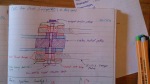
Joint concept for Z-Axis carriage to A-Axis Arm (A-Axis joint)
-
-
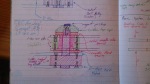
Some head clamp ideas
-
-
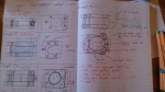
Joint concept for A-Axis to B-Axis Arms (B-Axis Joint)
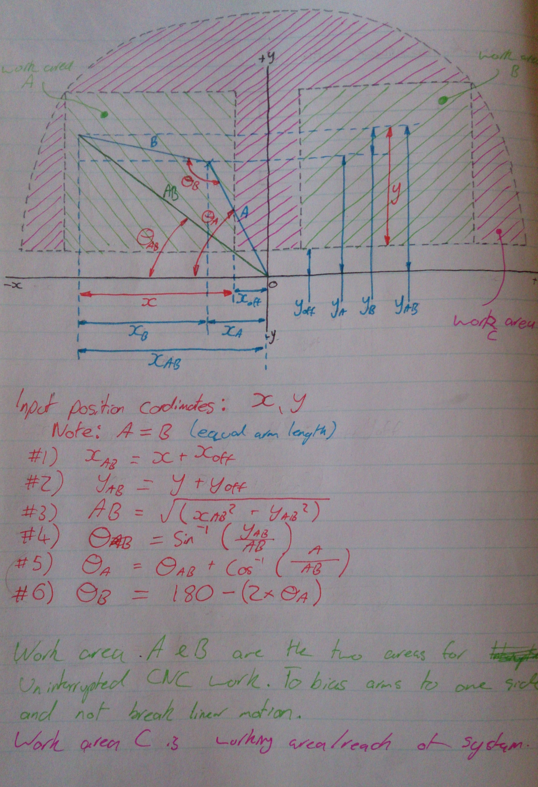
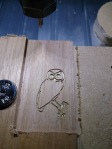
 I have also started to think about how this is going to calculate the angles it needs to position the A and B axis arms to put the head at the correct X:Y coordinate input. Its just basic trig, but it just needed a nice diagram to help see what was going on. It also helped to show the limitations for CNC work where it needs to move in uninterrupted motions. Like moving in a straight line without moving up off the work. The areas where this is permissible are simply shown as the light green boxes.
So for example it could draw a continuous line anywhere within these boxes. But (in some cases) if it was to draw a line out of one of these boxes. it would need to lift the pen off the paper, flip the pen to the other side of the arm, position where it stopped, then continue the line.
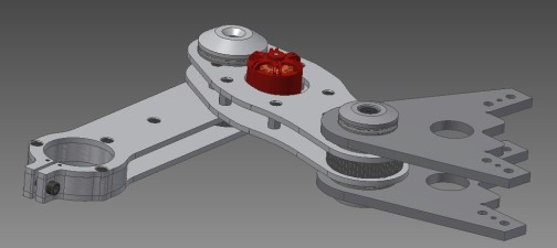
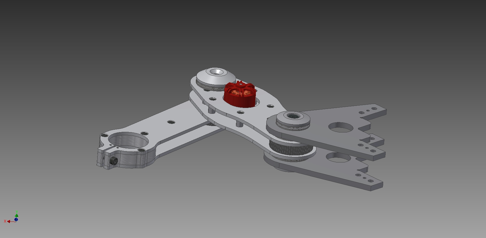
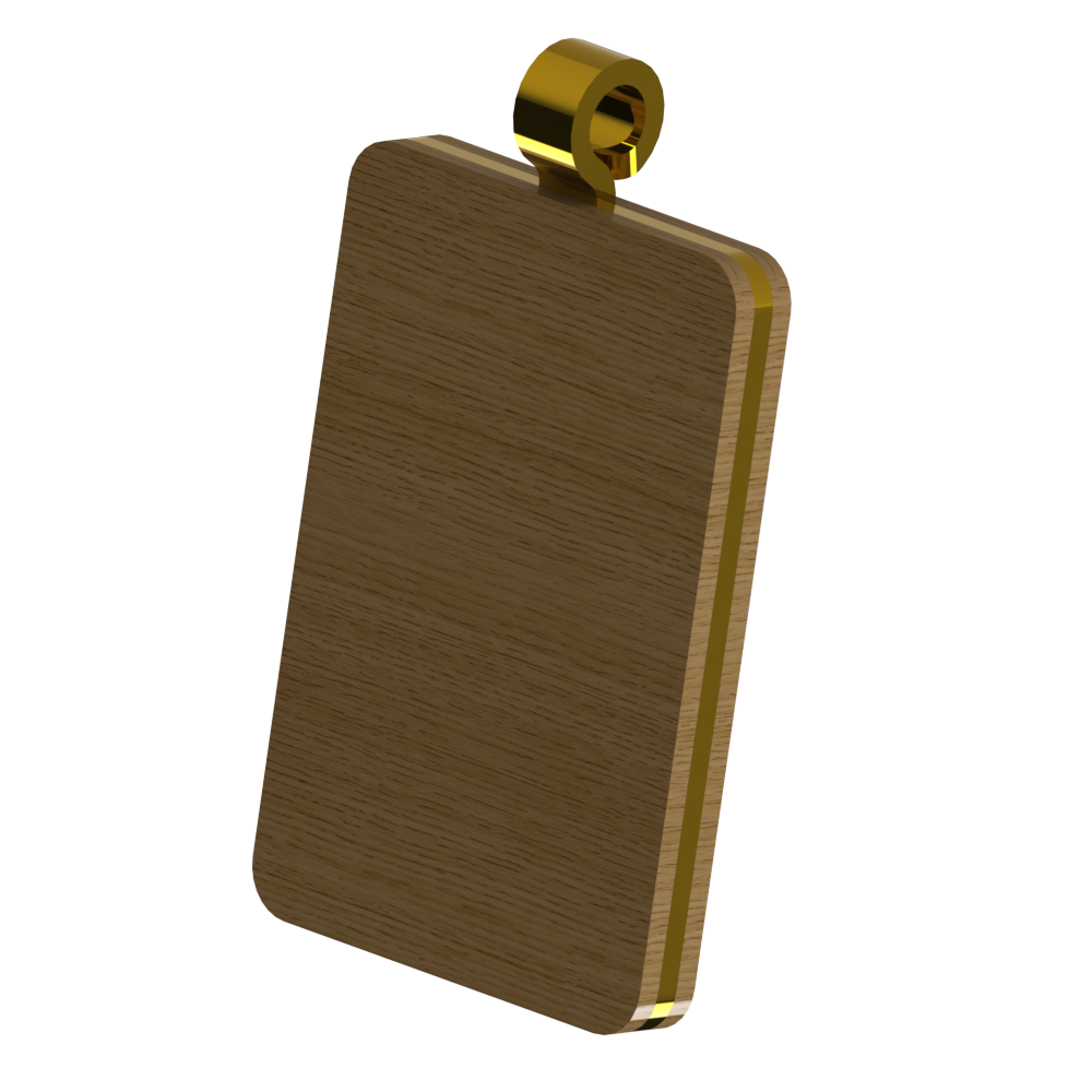
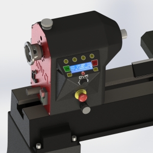
Now after all the initial concepts, I like to CAD up the basic design just to check there isn’t anything crucial I have missed on paper. So here is a peek of what the design is looking like so far.
Red is the motor inside the plates in the A-Axis arm. Dark Grey is the Z-Axis carriage. Light grey with the large hole in it is the B-Axis arm where the different heads are clamped into.


